Posts

Training Institute for Welding and NDT

Image
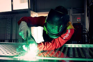
  Equipment’s required for Welding Institute set up. Welding is a process of joining metals or nonmetals such as plastic. There are different types of welding, and few of them are as below. SMAW- Shielded Metal Arc Welding (commonly called as ARC welding in the locality ) GMAW – Gas Metal Arc Welding – MIG /MAG GTAW – Gas Tungsten Arc Welding / TIG – Tungsten Inert Gas Welding FCAW – Flux Cored Arc Welding ERW – Electric Resistance Welding FSW – Friction Stir Welding SAW – Submerged Arc Welding LW – Laser Welding EBW- Electron Beam Welding GW- Gas Welding Ultrasonic welding And much more. A welding process can be done as Manual or Semi- Automated or Automatic / Robotic. To start up a  basic welding Institute it essential to have at least the basic three welding machines – SMAW , GTAW and GMAW welding machines And machines of Gas Welding , EBW and Laser Welding machines will be of added advantage. The training institute for welding should have a complete set up of Welding booth...

Material Testing

Image
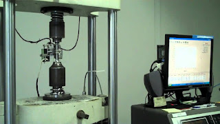
  Material testing Mechanical testing  have been designed to test several weld properties.Few other material testing techniques are Charpy V-Notch Toughness: Notch toughness is the capacity that a material possesses to  absorb energy  in the  presence of a flaw , such as a notch or crack. The material will likely exhibit a lower level of toughness. When a flaw is present in a material, loading induces a triaxial tension stres s state adjacent to the flaw. The material  develops plastic strains  as the yield stress is exceeded, near the crack tip. Notch-toughness is  measured with a variety of specimens  such as the  Charpy V-notch impact  specimen or the dynamic tear test specimen. As with regular impact testing the tests are often repeated numerous times with specimens tested at a different temperature. With these specimens and by varying the loading speed and the temperature, it is possible to  generate curves such as those s...

Mechanical Tests – Tensile Test – Impact test

Image
  Mechanical tests . Mechanical tests (exclusive of hardness) have been designed to test several weld properties. 1.    Tensile Test:    Tensile tests are conducted on specimens machined from a test weld and are used to measure the strength of the weld joint. Specimens are usually taken perpendicular to the weld, which is centered in the specimen.     Specimens are sometimes taken along the weld and consist entirely of weld metal. Specimens may have round or rectangular cross sections, depending on the requirements of  the applicable welding code. The testing machine applies a tensile force until ruptures .    From readings on the machine and measurements of the specimen before and after the test, properties such as yield point or yield strength, ultimate strength, and ductility are calculated.    Guided bend tests indicate a weld’s ductility . Test specimens are described as root-bend, face...

NDT institutes in Coimbatore

Image
  NDT Training: AQC- Advanced Quality Centre – NDT Institutes in Coimbatore provide World class trainings, certifications & online courses for Non-Destructive Testing, Welding Inspections, Painting Inspections,  welding course in  Coimbatore,  safety trainings & Industrial testing services. The trainings are provided by engineers experienced in global industries for more than decade. NDT in Coimbatore: AQC (Advanced Quality Centre) is an ISO 9001:2015 certified testing centre. We provide world class training and ISO certifications on NDT Non destructive testing course in Coimbatore.    We have a team of highly knowledgeable and professional engineers who trains our students on the NDT course and  Welding Course in Coimbatore . Our students get industry standard practical knowledge while pursuing the courses of NDT destructive testing , welding course in Coimbatore or welding inspector course in Coimbatore .   We assure 100% job guidan...

Welding Safety

Image
  Welding Safety with Gas Cylinders On an oxyacetylene system there will be three types of valves,  the cylinder valve, the regulator valve, and the torch valve . There will always be a set of three valves for each system, since  the gas in the cylinders is at high pressure. A broken off valve will release extremely high pressures, which could cause the cylinder to become an extremely deadly flying missile. For this reason, never move an oxygen tank around without its valve cap screwed in place. An oxygen tank is especially dangerous for the reason that the oxygen is at a pressure of  21 MPa (3000 lb./in² = 200 atm) . Oxygen cylinders are generally filled to approximately  2200 psi . The regulator  converts the high pressure  gas  to a low pressure  stream suitable for welding. It is not recommended to directly use high-pressure gas. Pressurized cylinders must at all times be handled with great care.  Shielding gases  such as carbon...

Safety and Precautions during welding

Image
  As in any welding process,   safety precautions  are very important. All information relating to the safe operation of the welding equipment and process must be fully understood before beginning work. A careless welder who does not observe some simple rules can cause a dangerous situation for everyone. The process of  arc welding creates several hazards  which must be guarded against. If the welding machine has the characteristics of a transformer or a motor-generator design, electrical energy is required as primary power to operate it. Useful safety information can be found in the Owner’s Manual that comes with each item of welding equipment. 1.  Electrical Shock: Welders must be concerned about the possibility of electrical shock. It should be remembered that electricity will always take the path of least resistance. A welder should never weld while standing in water. If wet working conditions exist, certain measures should be taken. Such measures inclu...

Pipe Line Isometric Drawings and P & ID Drawings

Image
  Pipe Isometrics   : Are drawings which shows details of Process pipe lines in a single line presentation , with details of pipes, pipe connections ( valves, flanges, nipples, reducers, end cap, elbow, etc), along with the dimensions and direction of  pipe line. Example of a Pipe Line Isometric Drawings is given below in figure-A Figure A: Example of Pipe Isometric Drawing P & ID :  is called as  Piping and Instrumentation Drawing , is a pictorial representation of  Pipeline in a single line diagram along with processing Equipments/ Instruments and storage tanks . Example of a P & ID is given below in figure-B Figure B : Example of P & ID  ( Piping and Instrumentation Drawing ) This Blog gives a detail study of P&ID and Pipe Isometrics, with details of What is P&ID Drawing What is an isometric drawing Symbols of Pipe Line Isometric Drawings What is pipe rolling / off-set We shall learn from the basics, Directions: Direction symbol ...