Mechanical Tests – Tensile Test – Impact test
Mechanical tests.
Mechanical tests (exclusive of hardness) have been designed to test several weld properties.
1. Tensile Test:
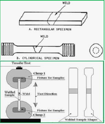
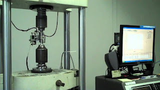
Tensile tests are conducted on specimens machined from a test weld and are used to measure the strength of the weld joint. Specimens are usually taken perpendicular to the weld, which is centered in the specimen.

- Specimens are sometimes taken along the weld and consist entirely of weld metal. Specimens may have round or rectangular cross sections, depending on the requirements of the applicable welding code. The testing machine applies a tensile force until ruptures.
- From readings on the machine and measurements of the specimen before and after the test, properties such as yield point or yield strength, ultimate strength, and ductility are calculated.
- Guided bend tests indicate a weld’s ductility. Test specimens are described as root-bend, face-bend, or side-bend, depending on the surface stretched in bending. Rectangular specimens for tensile tests are machined or ground to remove any weld reinforcement.
2. Impact Toughness:
The impact toughness of a material can be determined with a Charpy or Izod test. These tests are named after their inventors and were developed in the early 1900’s before fracture mechanics theory was available.
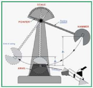
Impact properties are not directly used in fracture mechanics calculations, but the economic impact tests continue to be used as a quality control method to assess notch sensitivity and for comparing the relative toughness of engineering materials. The two tests use different specimens and methods of holding the specimens, but both tests make use of a pendulum-testing machine.

For both tests, the specimen is broken by a single overload event due to the impact of the pendulum. A stop pointer is used to record how far the pendulum swings back up after fracturing the specimen.
The impact toughness of a metal is determined by measuring the energy absorbed in the fracture of the specimen. This is simply obtained by noting the height at which the pendulum is released and the height to which the pendulum swings after it has struck the specimen .
The height of the pendulum times the weight of the pendulum produces the potential energy and the difference in potential energy of the pendulum at the start and the end of the test is equal to the absorbed energy.
At AQC, https://aqcinspection.com/ our scientists, technicians, engineers and inspectors are highly experienced. Experts in fields such as automotive technology, mechanical tests and electrical engineering, material science (metallurgy and polymers), chemicals, non destructive testing and industrial forensics.
Our services range from conducting analyses on failed engineering components and resolving failure issues for medical devices to investigating the causes of boiler tube failure in power plants, explosions and water losses.
We discover why materials and polymers fail and troubleshoot contamination issues. Our failure investigation services can be used to help improve product quality for consumer and retail goods if a product fails or does not perform as expected.
Visit our technical and career updates at our Blog site https://advancedqualitycentre.blogspot.com . or


Comments
Post a Comment