Types of Weld Joints
Here we are going to see about two types of weld Joints
- Groove Welds
- Fillet Welds Dimensions
1.1. Groove Welds:
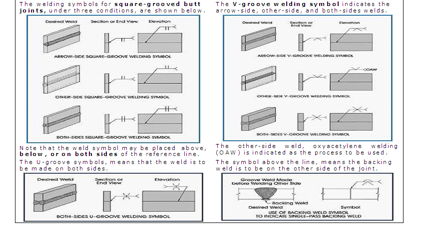
In the following figures, the perspective drawings of types of weld joints are shown at the left, looking at each joint from the arrow side. The illustrations cover only a small number of all possible symbols. The symbols shown here are those of the most common manufacturing application.
1.2 Fillet Welds Dimensions:
- Dimensions of fillet welds must be shown on the same side of the reference line as the weld symbol. When fillet welds are indicated on both sides of a joint and no general note governing the dimensions of the welds appears on the drawing.
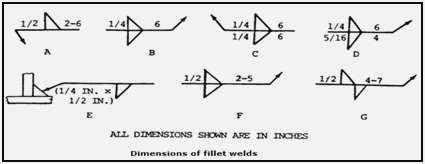
OBS.: If the dimensions of one or both welds differ from the dimensions given in the general note, both welds must be dimensioned. The size the fillet weld with unequal legs must be shown in parentheses to left of the weld symbol.
2. The length of a fillet weld, when indicated on the welding symbol, must be shown to the right of the weld symbol. When fillet welding extends for the full distance between abrupt changes in the direction of the welding, no length dimension need be shown on the welding symbol.
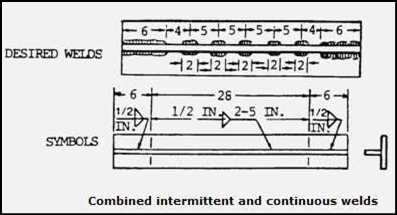
3. Fillet welding extending beyond abrupt changes in the direction of the welding must be indicated by additional arrows pointing to each section of the joint to be welded except when the weld-all-around symbol is used.

4. Unless otherwise specified, chain and staggered intermittent fillet welds on both sides shall be symmetrically spaced, or, when intermittent fillet welding is used by itself, the symbol indicates that increments are located at the ends of the dimensioned
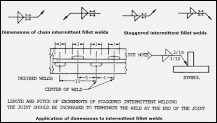
5. Surface contour. Fillet welds that are to be welded approximately flat, convex, or concave faced without recourse to any method of finishing must be shown by adding the flush, convex, or concave contour symbol to the weld symbol.
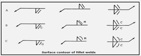
OBS.: Finish symbols used here indicate the method of finishing (“c” = chipping, “G” = grinding, “H” = hammering, “M” = machining), not the degree of finish.
we provide standard specifications for welding inspection procedures for all welding process and Brazing. We offer Welder Procedure Specification, Welder Certificate Renewal Process, Procedure Qualification Record, Welder Qualification Testing, welder Training and Welder qualification services in Coimbatore, Trichy, Salem, Erode, Chennai.
Please feel free to reach us https://aqcinspection.com/training/ to learn more about any of the methods in detail.
Visit our technical and career updates at our Blog site https://advancedqualitycentre.blogspot.com . or

Comments
Post a Comment