Weld Test Coupon Preparation
Bend Test Coupon Preparation
First the centerline on the plate shall be marked. Then another line 1.0 inch above the center line and another line 1 inch below the center line.
This is the section that can be used as an alternate coupon in the event of corner cracks with no evidence of slag inclusions.
Next, marking of the actual root and face bend specimens. Using the top and bottom line, another line a minimum of 1½ inches above.
The top line shall be marked and then 1½ inches below the bottom line. The minimum width of a test specimen needs to be 1½ inches wide.
After that the Welding Inspector shall mark the weld test coupons for a root and face bend in agreement with the welder, cutting them on a band saw.
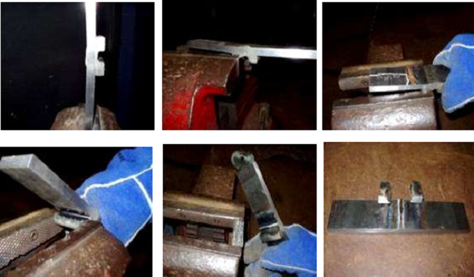
Backing Bar Removal:
The backing bar removal can be done using a vice and using a grinder on the center of the backing bar to gouge it, about 1/16” or so, to take the backing bar away from the back of the test plate.
The welder shall repeat this action until all of the backing bars are removed on the weld test coupons. The pictures below give a good illustration of how to remove a backing bar.
After the backing bar is removed, the face and the root of the weld shall be ground flush to the base metal. If the weld is ground past the base metal the test may be rejected for excessive removal.
After grinding down the root and face of the weld, a belt sander to round the square corners can be used, following by a buffing wheel to polish the weld area.
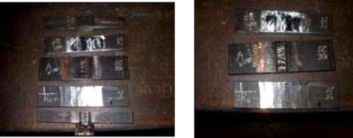
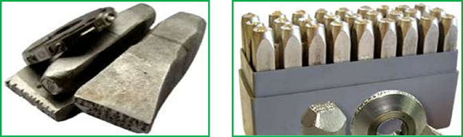
Test Coupons Stamps:
Generally the certified Weld Inspector uses steel stamps and dies for impact marking on metal, plastic, wood and other materials commonly using a hand held hammer as a percussion press, to mark chosen welding samples.
In general is used a two-digit number from 1 to 6 for the individual coupon, increasing in number in the direction of the weld. These will be cut from the finished weld later.
All required data per pass, by sample is recorded: preheat and interpassing temperatures, voltage, travel speed, electrode stick-out, everything. This system will help the Inspector when left with a pile of bent and broken coupons and have to figure out what went wrong.
As with visual evaluation, if your test samples don’t pass radiographic evaluation, don’t take additional action on the test sample. Figure out what went wrong and make a new test plate.
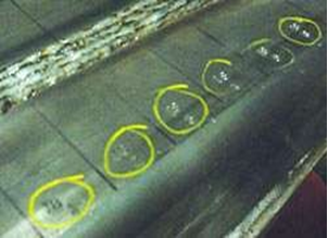
Each test coupon is marked with a steel stamp, to trace each sample back to its corresponding test.
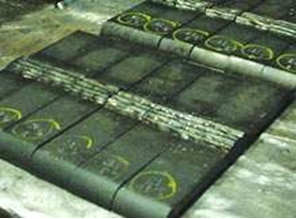
This weld test sample has been removed from a pipe and is ready to be cut with a saw.
After successfully completed these samples, the Inspector needs to start cutting the individual coupons. The correct code or welding specification will dictate the exact coupon size and location.
Typically, are necessary four (4) coupons for bending and two (2) for tensile testing. Finally, the Inspector will collect and document all test data on a Procedure Qualification Report (PQR) and develop a WPS, according to the code or welding engineering specification.
Basic Welding Process – Shielded Metal-Arc:
Filler Metal – Unless otherwise specified, the electrodes shall be E-7016, E-7018.
Base Metal – ASTM A709, Grade 36, or 50 or 50 W structural steel, ASTM A-252 steel pipe, ASTM A500 seamless steel structural tubing or A501 structural steel tubing
Type of current – AC, DC reverse (electrode positive) or DC straight (electrode negative).
Joint Design – Single bevel (with backing) double bevel, square butt welds, or fillet welds, and the thickness of the base metal.
Basic Welder Qualification:
Preparation of Base Metal – For materials up to 4 in. (100 mm) thick a mix surface roughness value of 1000 µin. (2 µmm) is permitted.
Joint Welding Design – Details that influence weld quality such as, welding the web first on H piling. The details determine the soundness, and influence the structural properties of the finished weld joint. Welding Position – flat, horizontal, vertical or overhead.
Preheat Temperature – Unless otherwise specified, the preheat temperature shall be as specified in the AWS Welding Code.
Interpass Temperature – Equal to minimum preheat temperature at all times. Maximum temperature is not critical provided the heat input during welding is not excessive.
we provide standard specifications for welding procedures for all welding process and Brazing. We offer Welder Procedure Specification, Welder Certificate Renewal Process, Procedure Qualification Record, Welder Qualification Testing, welder Training and Welder qualification services in Coimbatore,Trichy, Salem, Erode, Chennai.
Please feel free to reach us https://aqcinspection.com/training/ to learn more about any of the methods in detail.
Visit our technical and career updates at our Blog site https://advancedqualitycentre.blogspot.com . or


Comments
Post a Comment