Posts

Showing posts from May, 2022

Welding Safety

Image
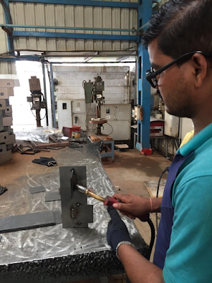
  Welding Safety with Gas Cylinders On an oxyacetylene system there will be three types of valves,  the cylinder valve, the regulator valve, and the torch valve . There will always be a set of three valves for each system, since  the gas in the cylinders is at high pressure. A broken off valve will release extremely high pressures, which could cause the cylinder to become an extremely deadly flying missile. For this reason, never move an oxygen tank around without its valve cap screwed in place. An oxygen tank is especially dangerous for the reason that the oxygen is at a pressure of  21 MPa (3000 lb./in² = 200 atm) . Oxygen cylinders are generally filled to approximately  2200 psi . The regulator  converts the high pressure  gas  to a low pressure  stream suitable for welding. It is not recommended to directly use high-pressure gas. Pressurized cylinders must at all times be handled with great care.  Shielding gases  such as carbon...
Safety and Precautions during welding

Image
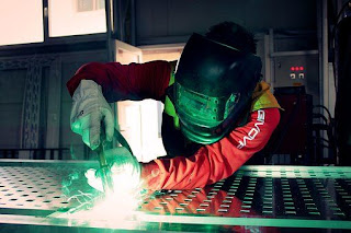
  As in any welding process,   safety precautions  are very important. All information relating to the safe operation of the welding equipment and process must be fully understood before beginning work. A careless welder who does not observe some simple rules can cause a dangerous situation for everyone. The process of  arc welding creates several hazards  which must be guarded against. If the welding machine has the characteristics of a transformer or a motor-generator design, electrical energy is required as primary power to operate it. Useful safety information can be found in the Owner’s Manual that comes with each item of welding equipment. 1.  Electrical Shock: Welders must be concerned about the possibility of electrical shock. It should be remembered that electricity will always take the path of least resistance. A welder should never weld while standing in water. If wet working conditions exist, certain measures should be taken. Such measures inclu...

Pipe Line Isometric Drawings and P & ID Drawings

Image
  Pipe Isometrics   : Are drawings which shows details of Process pipe lines in a single line presentation , with details of pipes, pipe connections ( valves, flanges, nipples, reducers, end cap, elbow, etc), along with the dimensions and direction of  pipe line. Example of a Pipe Line Isometric Drawings is given below in figure-A Figure A: Example of Pipe Isometric Drawing P & ID :  is called as  Piping and Instrumentation Drawing , is a pictorial representation of  Pipeline in a single line diagram along with processing Equipments/ Instruments and storage tanks . Example of a P & ID is given below in figure-B Figure B : Example of P & ID  ( Piping and Instrumentation Drawing ) This Blog gives a detail study of P&ID and Pipe Isometrics, with details of What is P&ID Drawing What is an isometric drawing Symbols of Pipe Line Isometric Drawings What is pipe rolling / off-set We shall learn from the basics, Directions: Direction symbol ...

Weld Crack

Image
  Weld crack   1.1. Cracking: If a weld crack is found, it must be removed and magnetic-particle inspection performed to ensure every point has been removed before re-welding. Weld Crack can occur on top of a weld bead, within the weld, or in the base metal. GMAW electrode wires are low hydrogen in content and have no flux coating to attract moisture, can help avoid cracking in the weld and heat-affected zones, if kept clean and dry. Spools or reels must be free of moisture both while being used and when being stored. A crack can easily occur on welding of aluminum, due to metal contraction as the weld pool cools, while the base metal remains hot. Cracks may be more numerous with aluminum, but they may also occur in stainless steel and galvanized materials. Cracks may occur if excess heat input is used for the particular thickness of material being welded, or steels with high carbon content, over 30 %, are likely to crack due to their hardness. Spatter: If there is a lot of sp...